Back to the top page
Back to Measurement Equipments 3
Stereo
Modulator VP-7637A ( Panasonic )
[Outline]
[Trouble-shoots]
[Power on drift of the
pilot signal level]
[Disassembling of the
clock
gen.] [Replace the
capacitors]
[Check the voltage of the memory back up battery ]
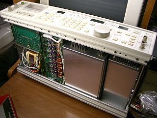
|
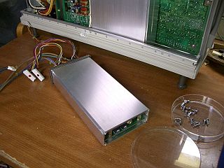
|
| Fig.1 The right module is the clock generator. |
Fig.2 Remove the clock
generator module. |
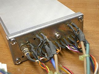
|
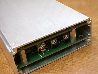
|
| Fig.3 Output cables from
the module. |
Fig.4 Another side of
the module. |
|
|
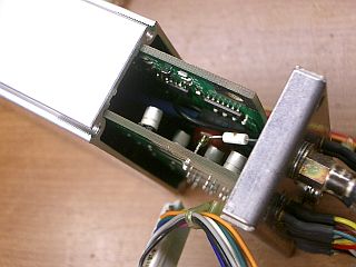
| Fig.5 Slide out the pwb
from the chassis. |
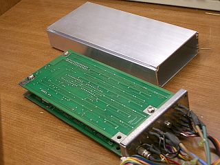
Fig.6 The pwb and the
chassis. |
|
|
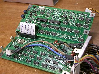
| Fig.7 Two pwbs are
connected. |
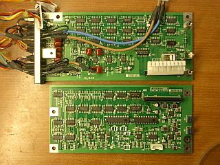
Fig.8 Same as Fig.7. |
|
|
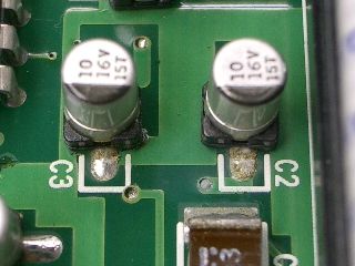
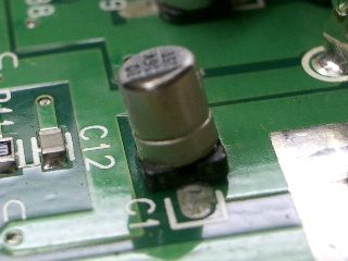
| Fig.9 Almost chemical
capacitors are leaked. |
Fig.10 Same as Fig.9. |


